What is a Mass Flow Controller?
A mass flow controller is a flow control device that measures mass flow and automatically controls it to a set flow rate. Fluids can be measured in two ways: mass flow (weight) and volume flow (volume). Mass flow controllers can accurately measure and control mass flow regardless of temperature and pressure variations. For this reason, mass flow controllers are widely used in semiconductor manufacturing processes, analytical equipment, and other situations where high repeatability and accuracy are required.
Mass flow is generally measured using thermal and Coriolis sensors. Thermal sensors measure mass flow based on the principle that temperature changes occur in response to fluid flow. Coriolis sensors, on the other hand, detect the Coriolis force generated by fluid vibration and measure mass flow based on this. The method should be selected according to the fluid (gas or liquid) and the conditions of use.
For more information, click here.
Mass Flow Controller Structure and Operation
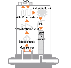
The main components of a typical thermal mass flow controller are a flow sensor, control valve, and bypass. Operation is automatic and consists of the following steps.

- Mass sensor is heated to measure fluid movement (mass flow rate)
- A bridge circuit converts the mass flow rate into an electrical signal
- The mass flow signal is converted to an electrical signal and amplified with an operational amplifier
- The signal is digitalized with an AD/DA converter
- The set flow rate is compared with the current flow rate in an arithmetic circuit
- PID control is used to drive the valve actuator
- Steps 1 to 6 are repeated (feedback control)
Principle of Mass Flow Controller Measurement
The flow sensor principle of the thermal mass flow controller is as follows

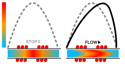
- Two electric heating wires are wound around a stainless steel capillary tube, which is heated to the same temperature. These electric heating wires are placed on the path through which the fluid flows.
- When the gas is shut off, the upstream and downstream electric heating wires maintain the same temperature and are not out of balance.
- However, as the gas flows, the upstream electric heating wire loses heat from the gas and flows downstream, changing the balance.
- To detect this change, a bridge circuit installed in the capillary tube is used. The bridge circuit is used to measure electrical signals and compare the signals from the upstream and downstream electric heating wires.
- The change in balance due to gas flow is converted into an electrical signal by a bridge circuit. This signal is measured as a mass flow rate.
Thermal mass flow controllers use this heat-based measurement principle to measure flow rates. This measured flow rate information is then fed back to the subsequent control circuitry, which performs control actions to bring the valve closer to the set flow rate by controlling the valve. Mass flow controllers from different companies may have different features depending on the flow sensor design and patented technology.
Lintec Mass Flow Controller Features
Lintec’s mass flow measurements are based on a unique low-temperature sensor structure; we started with the gas MFC production and were one of the first companies in the world to develop MFC for liquid applications.

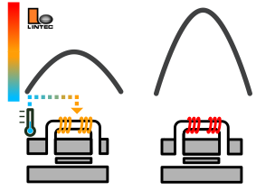
Lintec’s mass flow controllers employ a low-temperature sensing structure (ambient temperature compensated sensor) to enable high precision and high speed measurement. Our sensors have an original structure that prevents the sensor’s temperature from rising above the necessary level by having the ambient temperature feedback sent to the sensor.
- Less thermal damage to the sensor (longer life): The low-temperature sensing structure keeps the temperature of the flow sensor low. This results in less thermal damage to the sensor and longer product life cycle.
- Low risk of thermal decomposition of fluids (e.g. ozone can be controlled): Since the measurement is taken at lower temperatures than typical mass flow controllers, it is ideal for flow control of gases with a high risk of thermal decomposition, such as ozone. The thermal effect on fluids is minimized.
- High Speed flow control capability: The low-temperature sensor structure enables a response time that is overwhelmingly faster than that of conventional thermal sensors. Excellent performance when high-speed flow control is required.
This low-temperature sensor structure enables highly accurate and fast flow measurement and control.
Gas and liquid gas mass flow controller
Gas mass flow controllers are abbreviated as “MFC”; these fluid control devices were developed for precise gas control, predating the introduction of the liquid mass flow controllers. Gas volume tends to change under the influence of temperature and pressure according to the combined gas law, but the MFC measurement is unaffected by these factors, which enables it to automatically control flow rate to a set point with a built-in control valve. Thermal MFCs that utilize the principle of specific heat at constant pressure are the main type of mass flow controllers.
Liquid mass flow controllers are abbreviated as “LFC” and were developed for precise liquid flow control. Lintec was the first company in the world to develop a thermal liquid mass flow controller and thus contribute to technological innovation in semiconductor industry. In addition to the thermal type, there are also Coriolis and differential pressure LFCs.
Summary:
- Gas gas mass flow controllers are fluid control devices dedicated to gases, enabling precise flow control without being affected by temperature or pressure.
- Liquid mass flow controllers, abbreviated as “LFC”, provide precise liquid flow control. Lintec was the first company in the world to develop a thermal liquid mass flow controller.
MFC – FAQ
What is the difference between gauge pressure and absolute pressure?
Gauge pressure is atmospheric pressure, where 0 is 1 atm (approx. 101 kPa). Absolute pressure is defined as absolute vacuum at 0. Therefore, gauge pressure 0 kPa = absolute pressure 101 kPa.

